Introduction to wha-wha and gyrator:
There are a lot of information that one can find on internet about wha-wha pedal: how does it work [1], schematics [2, 3]. “What a wah does is clear – it is either a bandpass filter or an overcoupled lowpass filter that exhibits a resonant peak just at its lowpass rolloff frequency. The resonant peak can be moved up and down in frequency by the player, and this makes for a striking emulation of the human voice making a “waaaah” tone, or its tonal inverse, “aaaooow” [1], as ilustrated by the frequency response in figure 1.
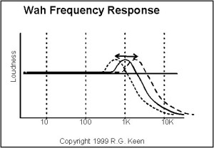 Figure 1: theoretical frequency response of a wha-wha pedal (from [1]).
The general way to create the resonance peak is using an RLC filter (R: resistance, L: inductance, C: capacitance), see for example figure 2.
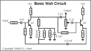
Figure 2: example of a wha-wha pedal circuit (from [1]).
Although resistance and capacitance are easy to find, the required inductance has to occupy a non negligible volume, and/or are expensive. However, it is possible to simulate an inductance with an operational amplifier. The circuit is named a gyrator, which is composed by an operational amplifier, and a set of adequate resistances and capacitors, as can be seen in the figure 3. When associating those components, we can calculate that the resulting behaviour is equivalent to the one of an inductance of value L1=R1xR2xC1, in series with the same resistance R1.
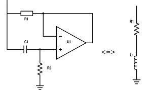
Figure 3: principle of the gyrator circuit.
The idea of replacing the inductance in figure 2 by a gyrator has already been suggested in the excellent book of D. Dailey [4], see for example figure 4, where a circuit without transistors but only an operational amplifier is used.
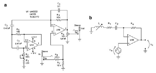
Figure 4: the inductance of figure 2 is replaced by a gyrator circuit (inductance simulator) (from [4]).
To our knowledge, there are no commercial wha-wha pedal based on that kind of circuit. The present article deals with the practical realization of the circuit proposed by D. Dailey, where we have implemented some modifications. Finally, some sound samples of the fabricated wha-wha pedal are presented.
Results
The few modifications brought to figure 4 are that first, we want to supply the operational amplifiers with a single supply (one 9V battery instead of two), as it is obviously a gain in space and perhaps money -it is not sure that the consumption will not be higher with only one battery. This has to be clarified in the future-. Also, we have added some coupling capacitor to reduce the overall noise. The resulting circuit of the gyrator-based wha-wha with single supply is given in the figure 5:
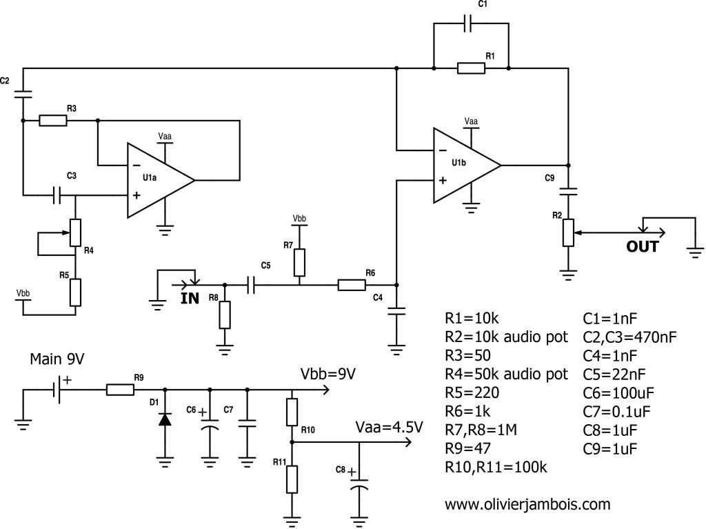
Figure 5: Schematic of the gyrator-based wha-wha that will be fabricated. ERRATUM : Vaa and Vbb are switched. Please visit my other blog on the gyrator circuit for wha-wha for the correct schematic.
Varying the value of the potentiometer R4, the resonance peak moves in frequency. To visualize it, we have performed some SPICE simulations. Those simulations appear in the figure 6. Increasing the resistance R4 from 9 ohms to 90 kohms, we see a clear evolution of the resonance peak from high frequency to low frequency, which is what we require to obtain the wha-wha effect. We also see a displacement of the bandwidth and its narrowing by increasing R4.
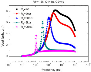
Figure 6: simulation of the evolution of the filter by varying the wha potentiometer (R4).
The circuit has been soldered on a perfboard for ease of use (see figure 8). The ensemble -perfboard/9V battery/potentiometers- has been inserted inside an old and cheap volume pedal. As the enclosure was not so big, we had to find a way to solder the components as closed as possible.
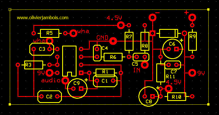
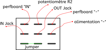 Figure 8: (Up) the parts were assembled on the perfboard that way, in order to gain space. The + and – symbols refer to the 9V battery pins, GND stands for ground, 9V’s dots and 4.5V’s dots have to be linked together by a wire. IN stands for the input, audio dot connects to the R2 potentiometer and wha’s dots connect to the wha potentiometer R4. (Down) the wiring of the 3PDT switch.
The result can be seen in figure 9. The on/off switch is a 3PDT switch to avoid tone sucking (read Ref. 5 for more information on true bypassing). The only problem we get that we have to mention is a pop when effect is switched ON. Further investigation are under way to solve this problem. Also we want to mention we first used a TL07x series operational amplifier at the beginning, and experimented an unexpected oscillation behaviour, which physical origin could not be determined. It occurred when having the wha potentiometer on the more resistive position and switching the pedal ON. This oscillation behaviour disappeared completely just by changing the operational amplifier with an other type, the NE5532P. Thus, this behaviour is attributed to the TL07x.

Figure 9: final result. The potentiometer on the right is the potentiometer R2 controlling output volume. On the left, there is an additional potentiometer that doesn’t appear in figure 5. The idea was to vary the value of R3 to be able to vary manually the value of the equivalent inductance. But the result was quite disappointing, so it has been removed from the figures of this article.
As a sound test, we present finally this video:
It could be interesting to compare this gyrator-based wha-wha with a commercial wha-wha (based on conventional RLC filter). This may be the object of a new article.
Conclusion and perspectives:
Here is a famous intro of one Jimi Hendrix song, freely developed:
And more sound samples:
You will find more music on www.olivierjambois/music
References:
[1] http://geofex.com/Article_Folders/wahpedl/wahped.htm
[2] http://diy.smallbearelec.com/Projects/ISeeWah/ISeeWah.html
[3] http://www.generalguitargadgets.com/how-to-build-it/technical-help/schematics/
[4] Denton J. Dailey, Electronics for guitarists, Springer
[5] http://www.geofex.com/article_folders/bypass/bypass.htm
Hello. Thank you for writing this.
Just some clarification around the pots if you don’t mind. The output voltage divider (r2) is the wah pot (the Hot Potz for example). And r4 is the frequency pot, or is that the other way around and r4 is the pot controlled by the treadle?
Did you commit to using a 1k instead of a pot there, or did that also use a pot to control the Q/size of peak?
Thanks.